Siemens NX · Thermal Engineering · C101 Copper
High-Flux Liquid Cooling
A cold plate architecture study comparing two design paths: a compact microchannel plate optimized for low pressure drop, and a jet impingement extension for localized hotspot cooling.
Each design is shown as its own engineering package: concept, flow path, CAD preview slot, specifications, and simulation plan. This avoids mixing the old render archive with the new design direction.
Compact Diffuser Microchannel Cold Plate
The manufacturable baseline. Compact inlet and outlet plenums distribute flow into a dense micro-fin field without unnecessary dead volume, replacing the earlier oversized manifold-bath geometry.
Compact Diffuser Microchannel
Reserved for the updated NX render once the compact diffuser, bolt layout, and 50 × 50 mm fin field are finalized.
| Footprint | 120 × 100 mm target |
| Active area | 50 × 50 mm fin field |
| Inlet / outlet | Side-entry, side-exit |
| Plenums | 5–8 mm compact diffuser / collector |
| Priority | Low ΔP, uniform flow |
| Revision | Bath manifold removed |
Thermal study
Base temperature distribution, junction-adjacent ΔT, and heat spreading across the 50 × 50 mm micro-fin region.
Flow / ΔP analysis
Pressure drop, velocity uniformity, and channel-to-channel maldistribution through the compact diffuser layout.
Jet Impingement Cold Plate with Pin-Fin Target Zone
The high-performance hotspot design. Direct jet stagnation over a pin-fin target zone increases local heat transfer at the chip center, accepting higher pressure drop and manufacturing complexity as tradeoffs.
Jet Impingement + Pin-Fin
Reserved for the updated NX render once the jet plenum, nozzle plate, standoff gap, and collector exits are finalized.
| Architecture | Top-fed jet impingement |
| Jet layer | Nozzle plate + standoff gap |
| Standoff | 2 mm above pin fins |
| Target zone | Pin fins aligned to heat source |
| Flow exit | Bilateral or perimeter collector |
| Priority | Hotspot suppression, high HTC |
Hotspot thermal study
Local temperature reduction and heat-transfer enhancement under direct jet impingement at the chip-center region.
Jet flow analysis
Jet velocity profiles, stagnation zones, outlet balance, and pressure-drop tradeoffs through the nozzle array.
Microchannel / Low ΔP
Compact diffuser with side inlet/outlet routing for lower pressure drop and more manufacturable flow distribution.
Jet Impingement / Hotspot
Top-fed nozzle array with standoff gap and pin-fin target zone for concentrated high-flux hotspot control.
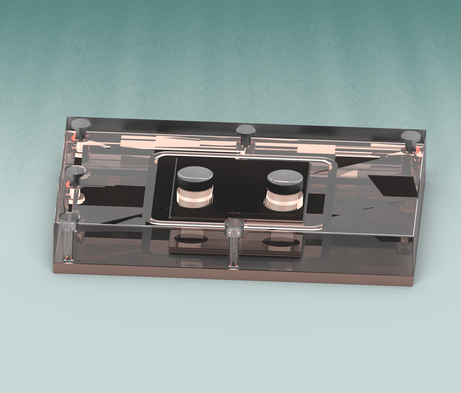
These renders document the earlier transparent manifold-bath geometry. They are no longer the active build direction, but are kept to show the design evolution that led to the compact diffuser and jet impingement paths.

Micro-fin region closeup
Study 01 · Superseded
Internal geometry detail
Study 02 · Superseded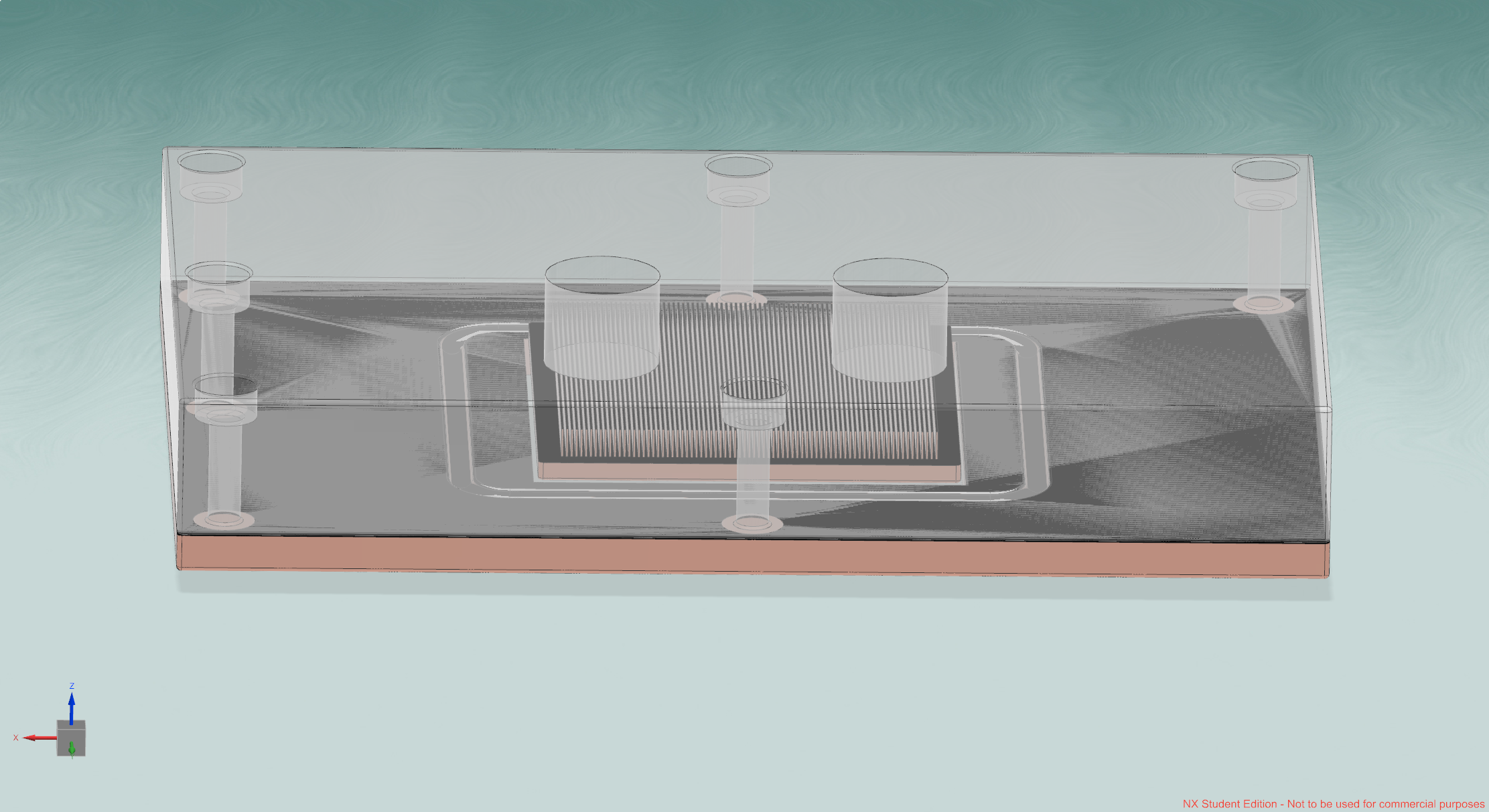
NX development snapshot
Study 03 · SupersededReal-world liquid-cooling architectures used as context for this independent design study.

Channel spacing, thermal gradients, and coolant routing reference.
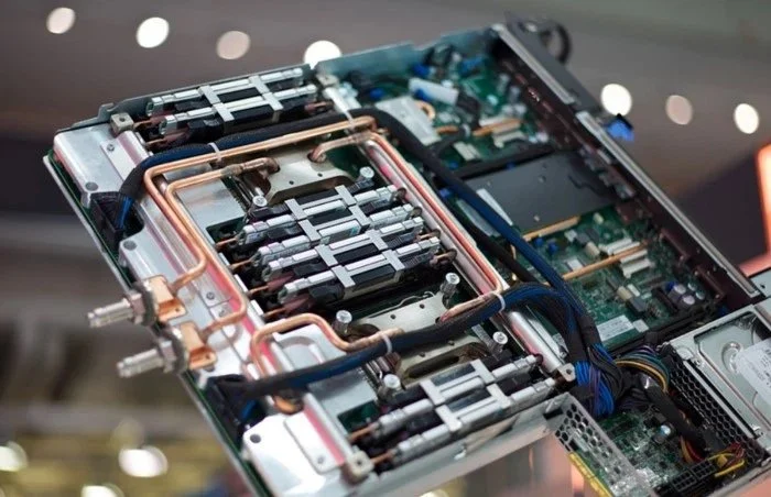
Manifolded copper cold plate packaging at server scale.

Multi-chip manifolded cooling for high-power accelerator platforms.