Plasma Mg Evaporation Model
NH3 plasma heating with coupled Electric Currents + Heat Transfer modeling across a 0–90 A current sweep.
COMSOL multiphysics study of magnesium disc heating and evaporation-risk behavior during plasma exposure. The model compares current loading and disc-thickness sensitivity to identify a more stable thermal operating window for nanoparticle synthesis.
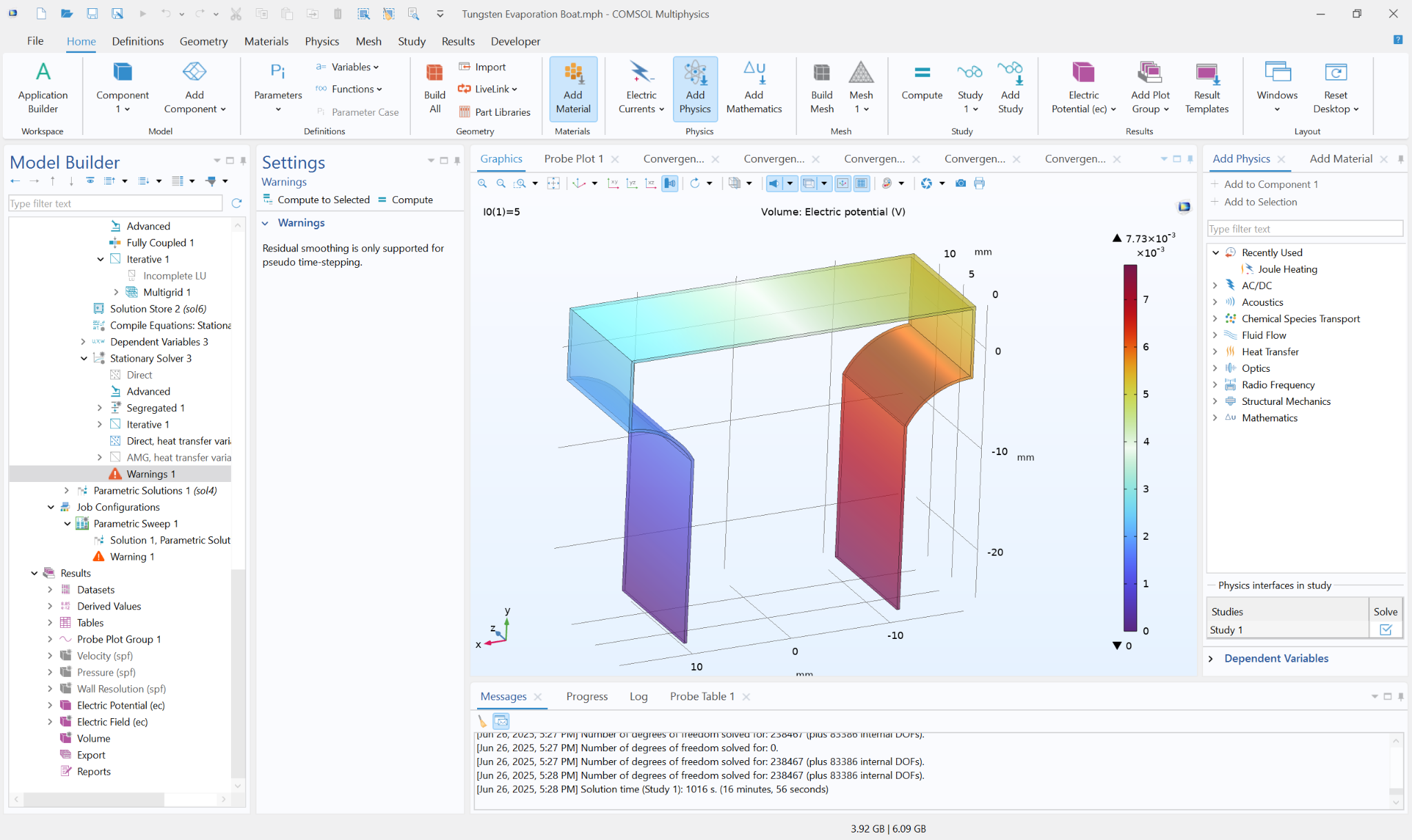
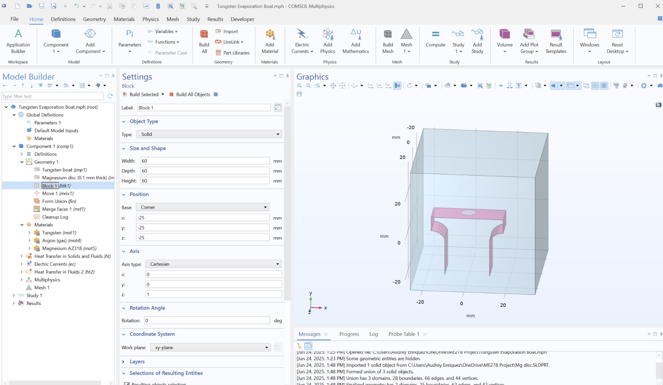
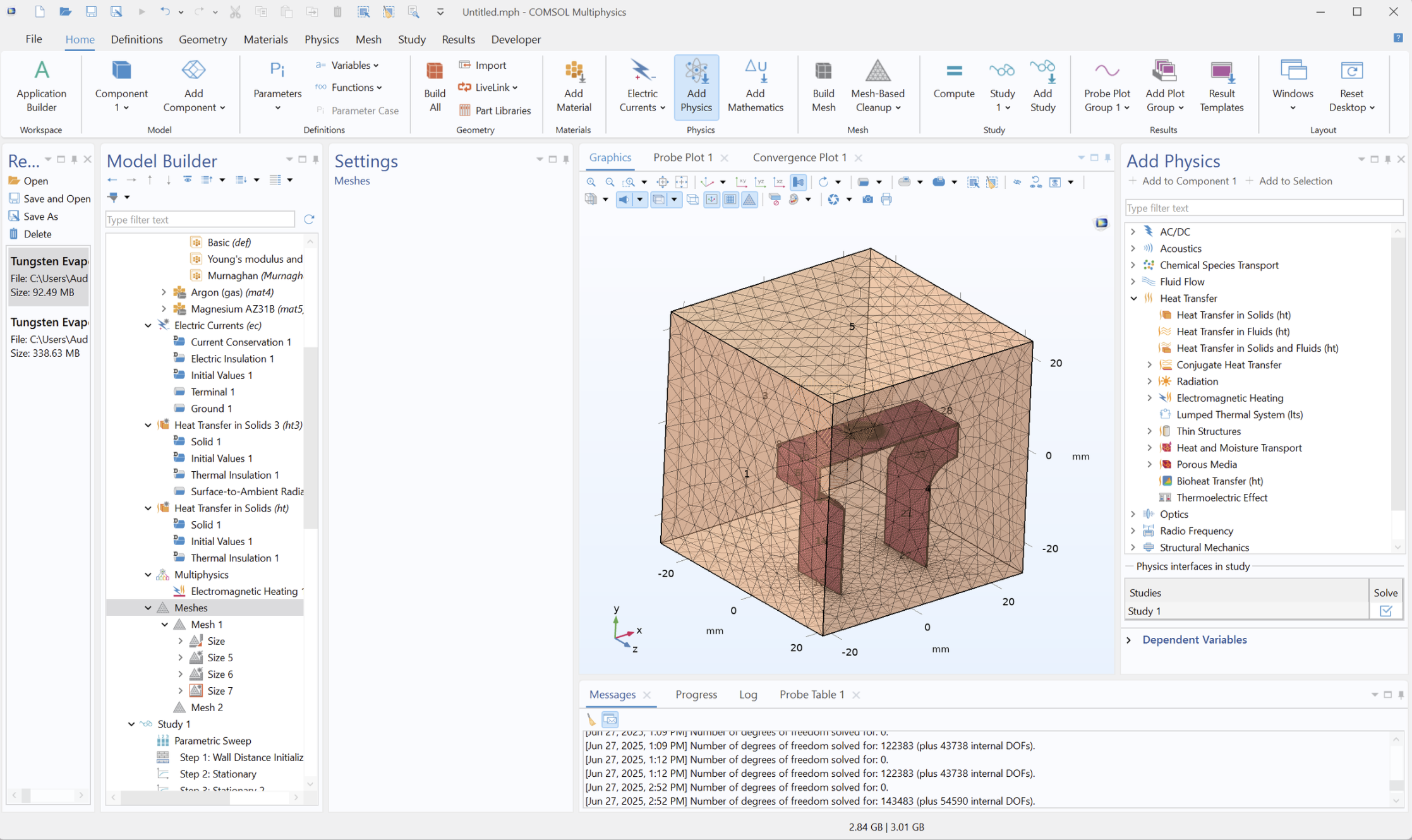
Geometry + Mesh Evidence
The geometry and meshing strategy resolve high-current regions while keeping the full reactor domain computationally efficient.
Model assumptions and limitations
- Evaporation proxy: latent-heat sink boundary used as a relative Mg-loss indicator.
- NH3 plasma: represented through enclosure boundary conditions rather than full plasma chemistry.
- Radiation: simplified Stefan–Boltzmann boundary treatment.
- Contact resistance: treated as a sensitivity parameter affecting peak gradients.
- Mesh convergence: checked to confirm key thermal trends were not dominated by element size.
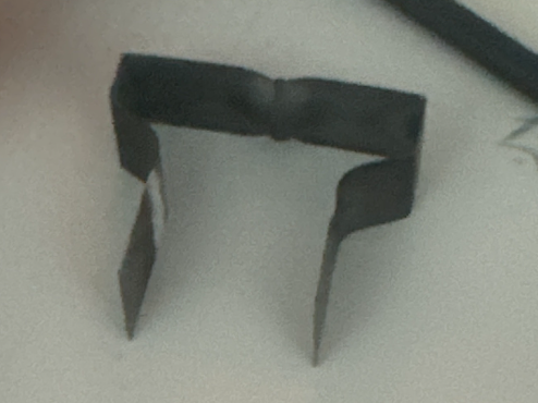
Experimental Reactor Context
Experimental hardware provides physical context for the modeled geometry and operating constraints.
Further lab system details and SOP contribution
The simulation work was grounded in a physical RF plasma reactor system used in the lab for Mg evaporation and nanoparticle synthesis. These images provide additional context behind the geometry, operating constraints, and hardware assumptions used in the model.
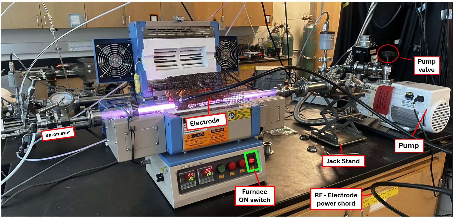
- Reactor architectureQuartz-tube plasma reactor with rotational drive and furnace heating.
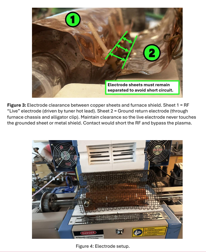
- Electrical setupRF electrode coupling and grounding configuration.
- Gas handlingHydrogen and argon flow control with vacuum stabilization.
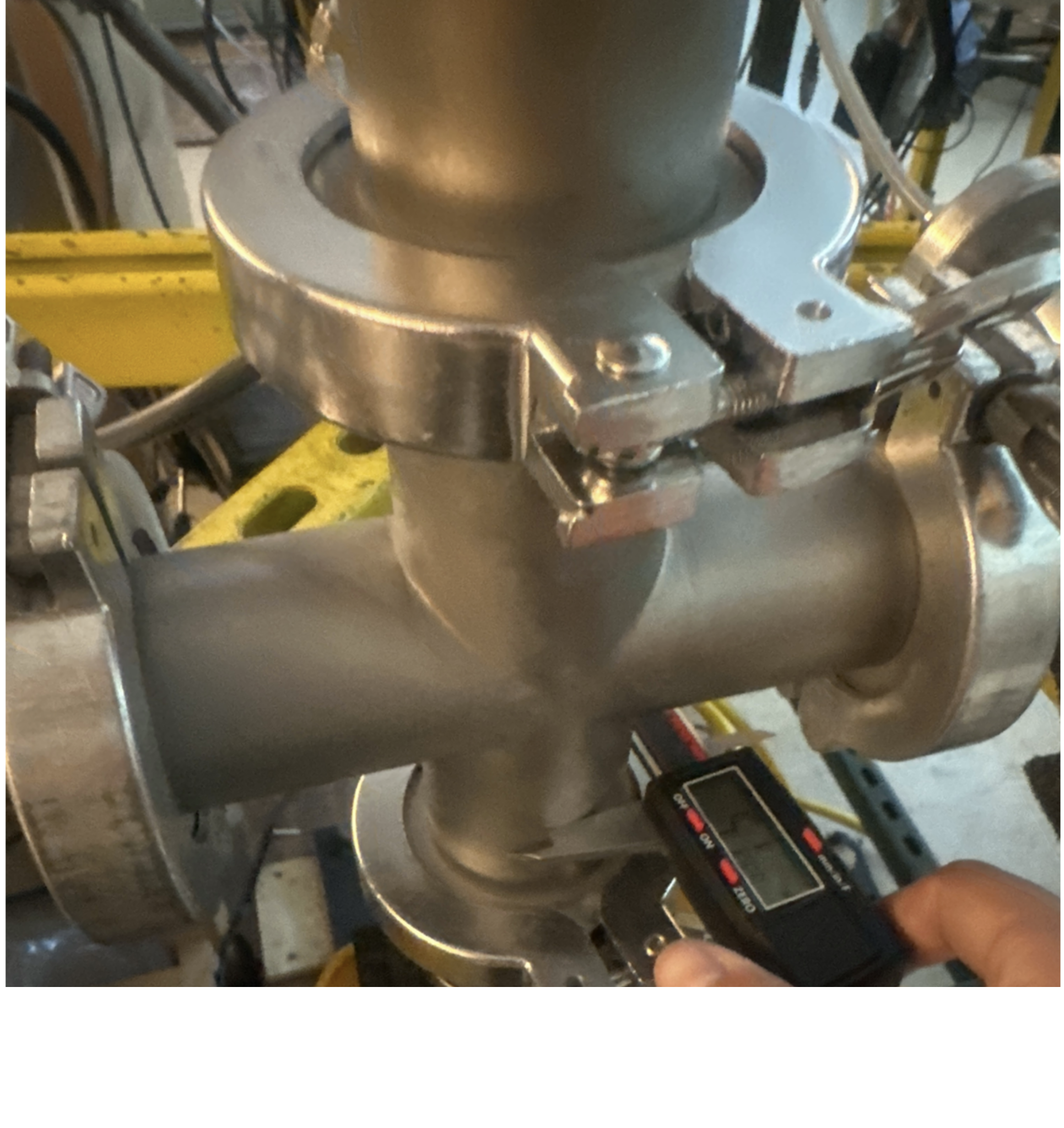
- Pre-ignition checksMechanical alignment and electrode-clearance verification.
- Procedure controlStartup, gas stabilization, RF ignition, and shutdown documentation.
- Validation supportIR thermography workflow used to compare model trends with observed heating behavior.
Selected References
- Kortshagen et al., Nonthermal Plasma Synthesis of Nanocrystals, Chemical Reviews.
- Wagner et al., Low-Temperature Plasma Hydrogenation of Mg Nanoparticles, Journal of Applied Physics.