Thermal Isolation Bracket — Conduction Path Analysis
Three bracket geometries were created in Siemens NX to reduce conductive heat leakage and compared in Simcenter 3D.
Model
Heat conduction follows q = (k · A / L) · ΔT.
• Aeff = remaining conductive cross-section
• Leff = effective conduction path length
Thermal resistance scales as Rth ≈ Leff / (k · Aeff). Higher Leff and lower Aeff improve isolation.
Setup
Base plate: 100 × 80 mm
Thickness: 8 mm
Material: Al 6061
Fasteners: Ø6.6 through, counterbore 11 mm
Key Result
The serpentine multi-pass geometry produced the strongest expected thermal isolation by extending the conduction path and reducing the remaining conductive cross-section.
Straight slots reduce conductive area, but heat still crosses through relatively direct remaining bridges.
- Aeff decreases.
- Moderate increase in thermal resistance.
- Simplest machining; baseline case.
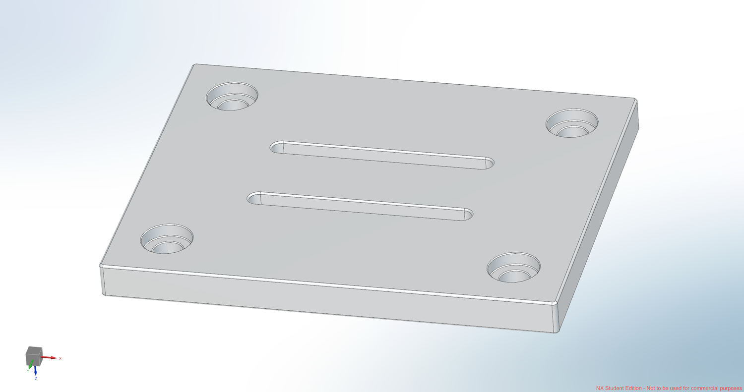
Design 1 — Baseline (2 slots)
Straight slots reduce conductive area, but heat still crosses through relatively direct remaining bridges.
- Aeff decreases.
- Moderate increase in thermal resistance.
- Simplest machining; baseline case.
A center slit further restricts the main heat bridge while preserving symmetry; radiused ends reduce stress concentration.
- Smaller Aeff through the main heat bridge.
- Higher expected thermal resistance than Design 1.
- Lower stiffness than the baseline.
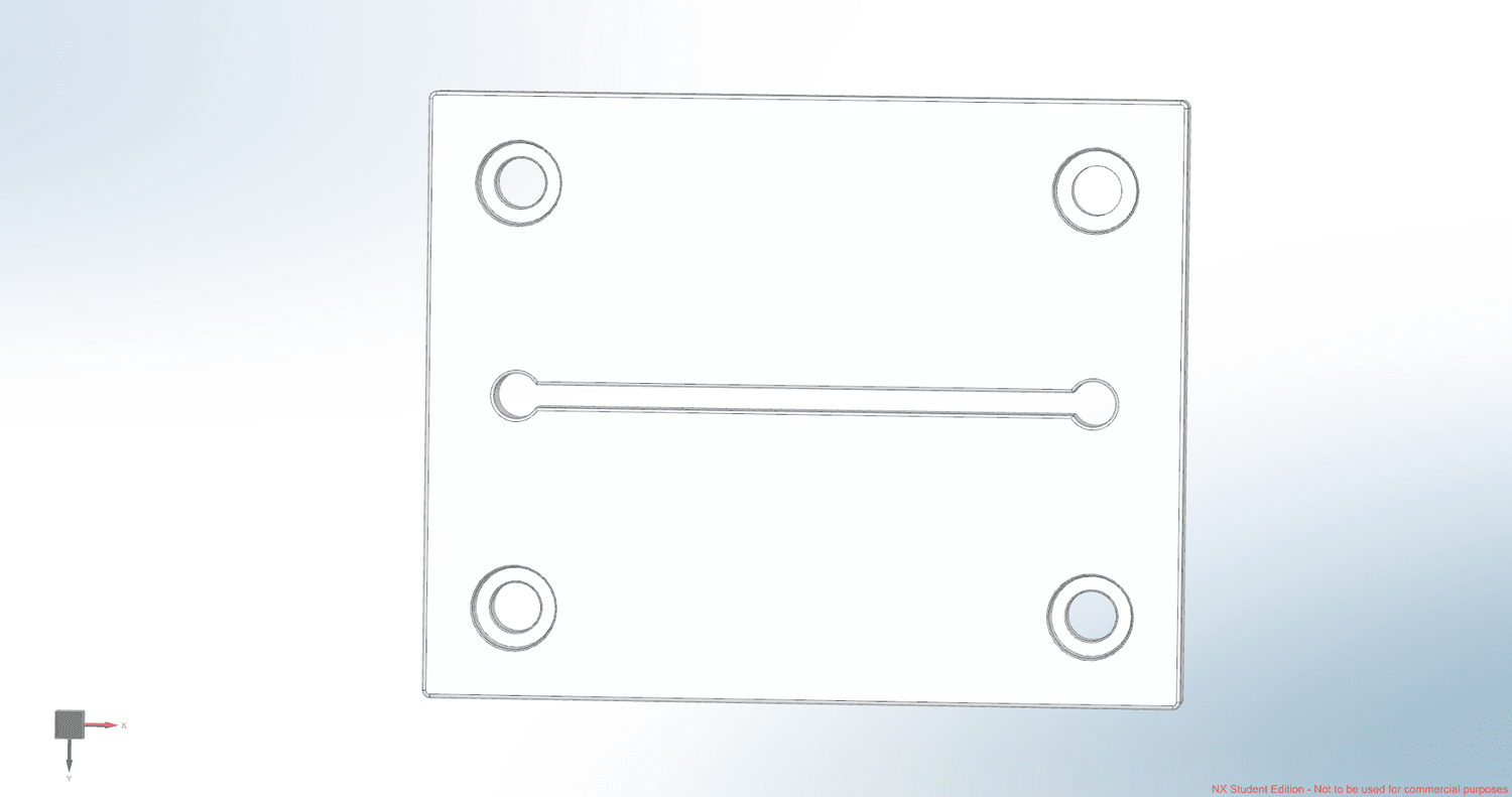
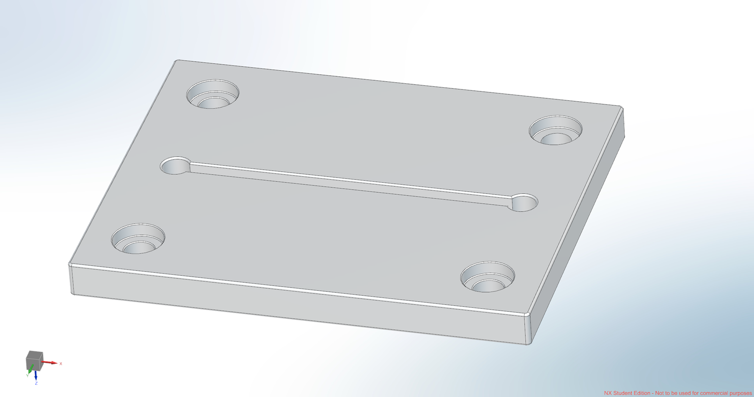
Design 2 — Center slit with radiused ends
A center slit further restricts the main heat bridge while preserving symmetry; radiused ends reduce stress concentration.
- Smaller Aeff through the main heat bridge.
- Higher expected thermal resistance than Design 1.
- Lower stiffness than the baseline.
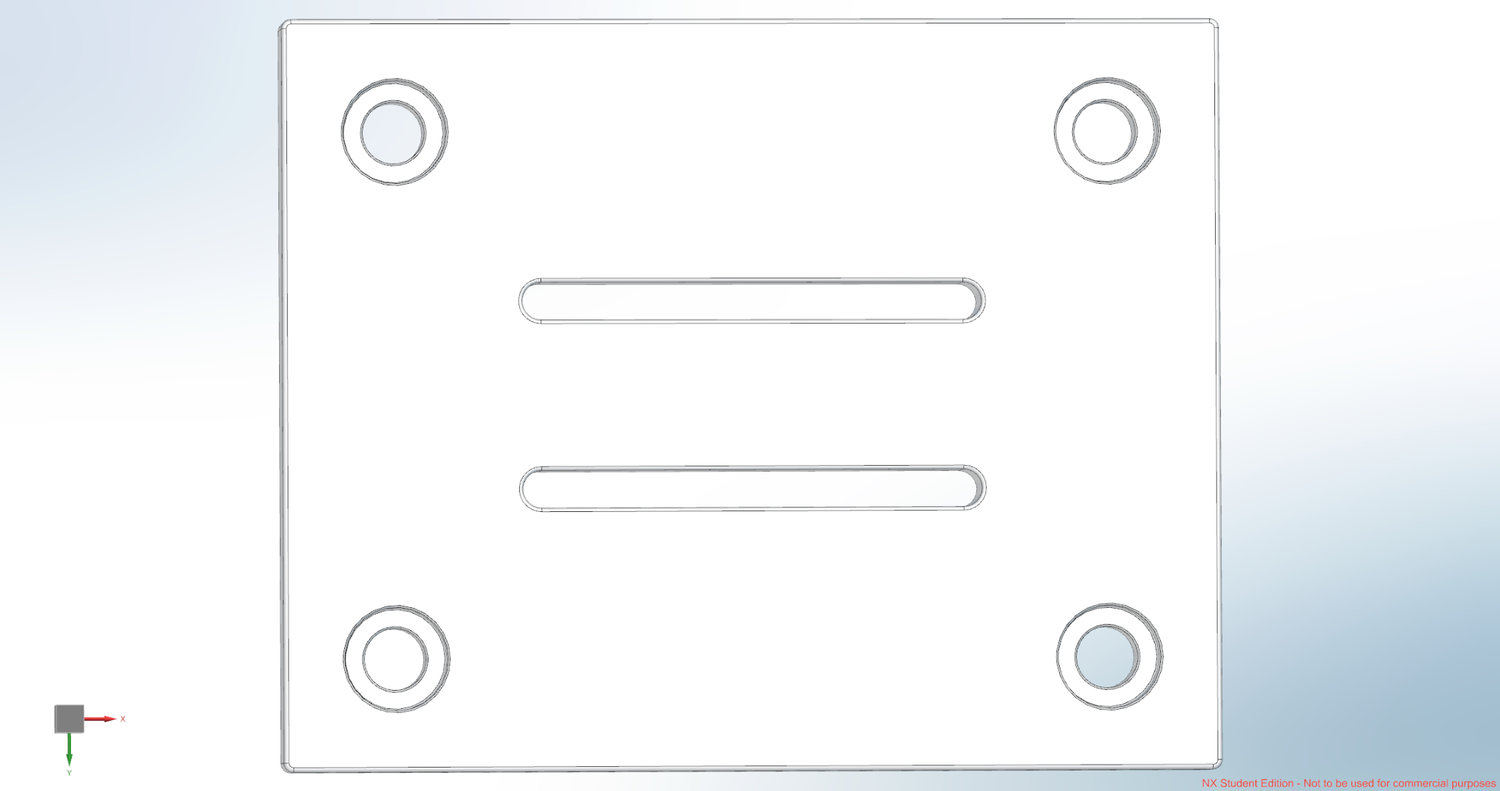
The serpentine slot increases conduction path length and reduces effective conductive cross-section, giving the highest expected thermal resistance.
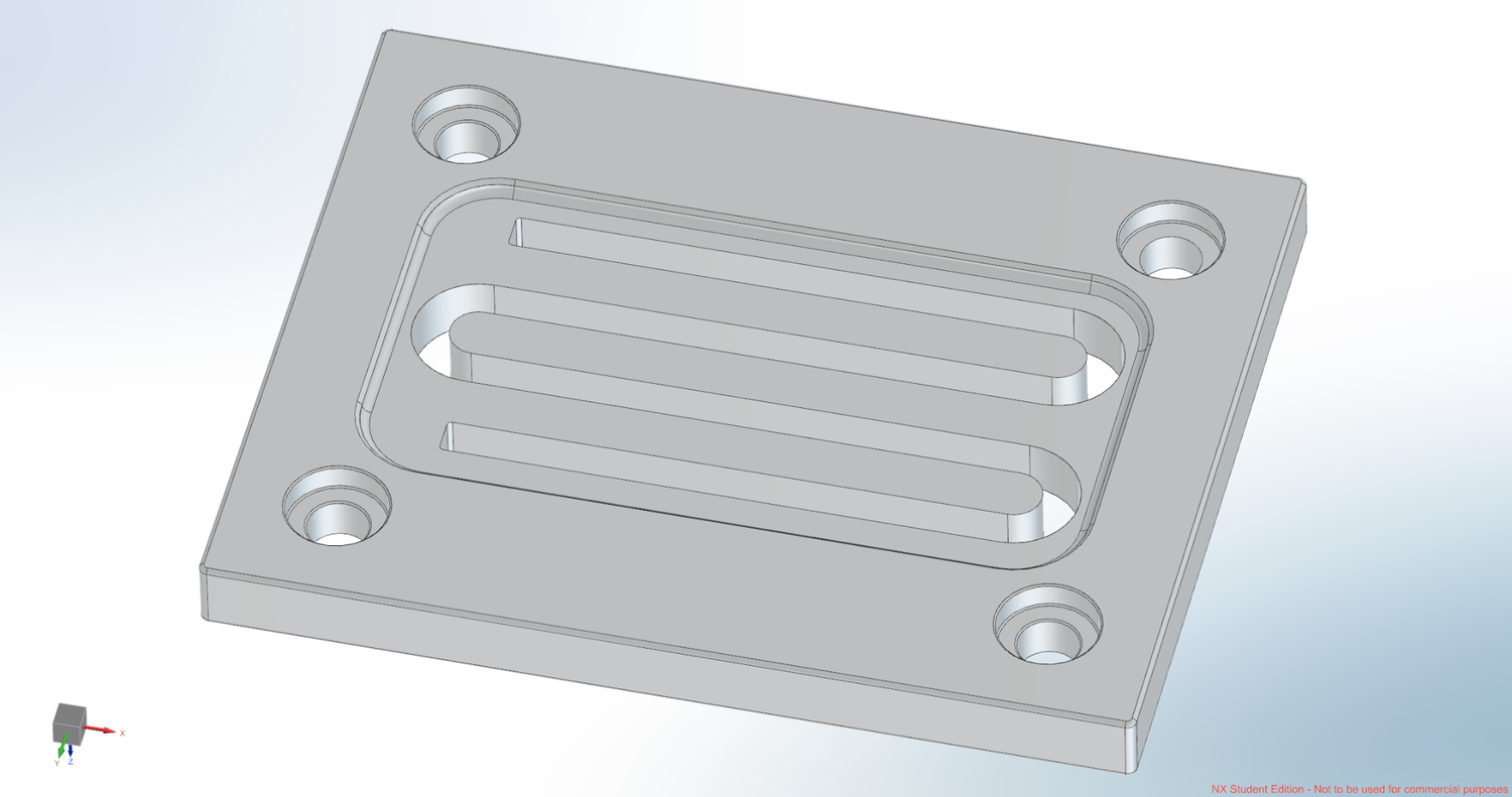
- Leff increases and Aeff decreases.
- Lowest expected conductive heat leak.
- Tradeoffs: more machining, reduced stiffness, and ligament stress requiring structural review.
Best expected isolation of the three concepts.
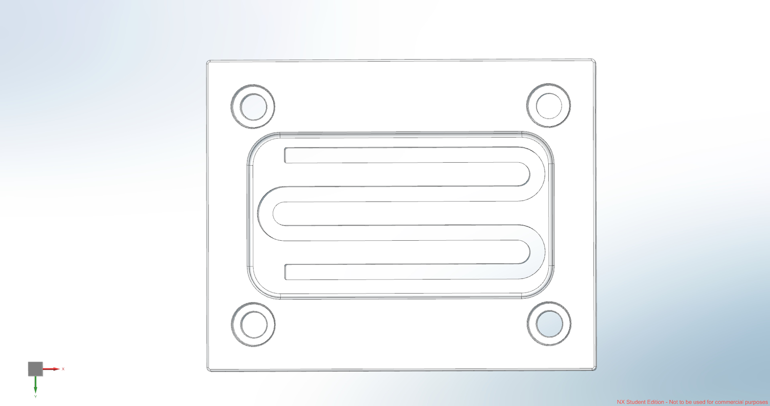
Design 3 — Serpentine multi-pass slot
The serpentine slot increases conduction path length and reduces effective conductive cross-section, giving the highest expected thermal resistance.
- Leff increases and Aeff decreases.
- Lowest expected conductive heat leak.
- Tradeoffs: more machining, reduced stiffness, and ligament stress requiring structural review.
Best expected isolation of the three concepts.
A 1.5 mm recessed pocket was added to further reduce direct conduction between the hot region and the mounting interface.
- Thermal goal: reduce conductive cross-section and increase local resistance.
- Mechanical goal: preserve enough material for stiffness and fastener load transfer.
Thermal relief pocket
A 1.5 mm recessed pocket was added to further reduce direct conduction between the hot region and the mounting interface.
- Thermal goal: reduce conductive cross-section and increase local resistance.
- Mechanical goal: preserve enough material for stiffness and fastener load transfer.
With constant k and ΔT, heat leak scales with Aeff/Leff. Expected ranking: Design 3, then Design 2, then Design 1.
| Design | Geometry change | Thermal lever | Tradeoff |
|---|---|---|---|
| 1 | Two straight slots | Aeff ↓ | Simple manufacturing |
| 2 | Center slit + radiused ends | Aeff ↓↓ | Lower stiffness than 1 |
| 3 | Serpentine multi-pass | Leff ↑↑ and Aeff ↓ | Machining + ligament checks |
Design ranking
With constant k and ΔT, heat leak scales with Aeff/Leff. Expected ranking: Design 3, then Design 2, then Design 1.
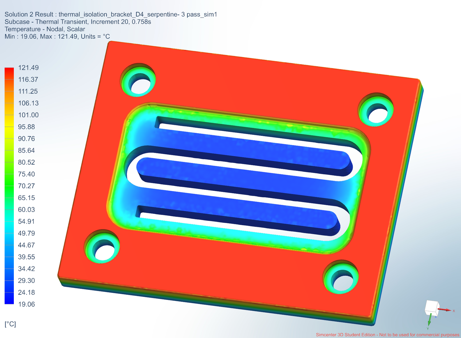
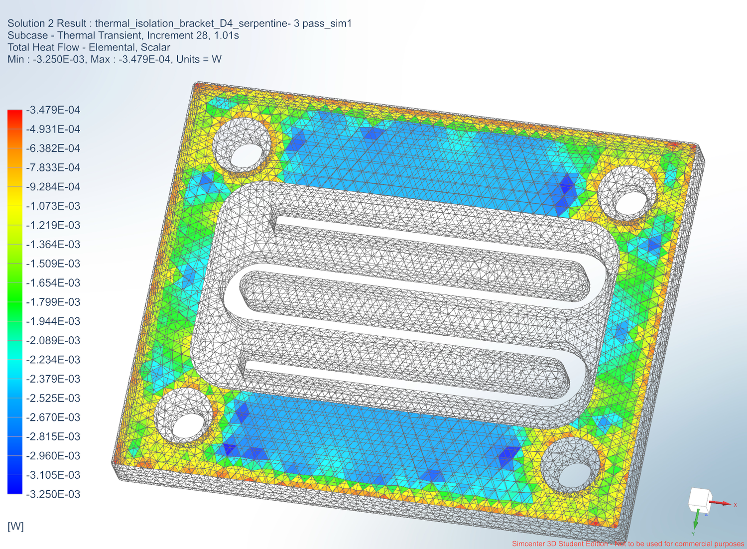
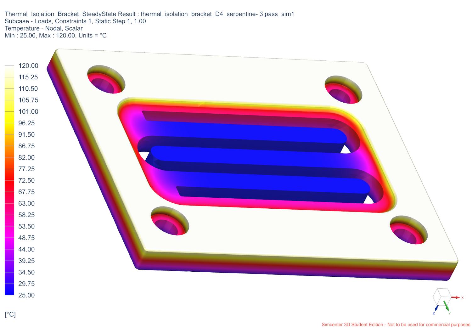
Simcenter 3D Study
Simcenter 3D was used to compare temperature distribution and heat-flow redirection through the serpentine pocket geometry.